archiveFeb 10, 2021
ARM Load/Store Multiple Register Instructions
How ARM and Thumb LDM/STM move register sets, the four addressing modes, and how those instructions implement push/pop and nested subroutine frames.
Load and store multiple registers
- The ARM and Thumb instruction sets include instructions that load and store several registers from or to memory in one shot.
- Multiple-register transfers move many register contents without a long chain of single transfers.
- Common uses: block copies, and stack work on subroutine entry and exit.
- Preferring a multiple-register transfer over a sequence of single data transfers buys you a few things:
- Smaller code
- One instruction fetch instead of many
- On uncached ARM processors, the first word of an LDM/STM is a non-sequential memory cycle; later words can be sequential
- Sequential memory cycles are usually faster
ARM LDM and STM
- A single LDM or STM can load or store a subset of the 16 general-purpose registers.
LDM
LDM {cond} address-mode Rn{!}, reg-list{^}

4 addressing modes:
LDMIA / STMIA
LDMIB / STMIA
LDMDA / STMDA
LDMDB / STMDB
cond
- Optional condition code.
address-mode
- Addressing mode for the instruction:
- IA: increment after
- IB: increment before
- DA: decrement after
- DB: decrement before
Rn
- Base register for the transfer.
- The address in that register is the start address.
- Do not use r15 (pc) as the base.
!
- Write-back on the base register.
- When present, the base address updates after the transfer.
- It moves by one word per register in the list (up or down, depending on the mode).
Register-list
- Comma-separated symbolic register names and ranges inside braces.
- At least one register is required.
- Ranges use a dash:
{r0, r1, r4-r6, pc}. - If the base register Rn appears in the list, do not combine that with write-back/store in ways the architecture forbids.
^
- Do not use this option in User or System mode.
- STM syntax matches LDM aside from a few details of what
^does.
Building a stack with LDM and STM
-
Load/store multiple can update the base register.
-
For stack ops the base is usually the stack pointer, r13.
-
That means one instruction can push or pop several registers.
-
The same instructions cover several stack styles.
Descending vs ascending
- A stack can grow downward from high addresses, or upward toward higher addresses.
Full vs empty
-
The stack pointer can point at the last used item (full stack) or at the next free slot (empty stack).
-
Instead of raw increment/decrement suffixes, you can use stack-oriented names:
Stack type				Push			Pop
Full descending		STMFD (STMDB)	LDMFD (LDMIA)
Full ascending		STMFA (STMIB)	LDMFA (LDMDA)
Empty descending	STMED (STMDA)	LDMED (LDMIB)
Empty ascending STMEA (STMIA) LDMEA (LDMDB)- Exercise 1
LDMXX r10, {r0, r1, r4}
STMXX r10, {r0, r1, r4}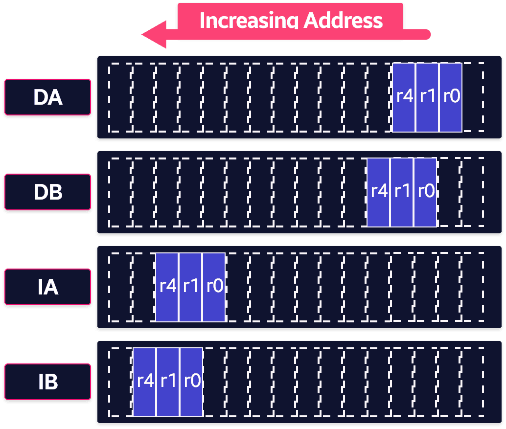
- Exercise 2
STMFD    r13!, {r0-r5}  ; PUSH onto a full descending stack
LDMFD    r13!, {r0-r5}  ; POP from a full descending stack
Stack registers for nested subroutines
- Stack ops matter most on subroutine entry and exit.
- On entry, push the working registers you need.
- On exit, pop them back.
- If you also push the link register on entry, you can call further subroutines without losing the return address.
- On exit you can pop pc directly from the stack instead of popping lr and then moving it into pc.
subroutine  STMFD   sp!, {r5-r7,lr} ; push work registers and lr
            ; code
            BL      somewhere_else
            ; code
             LDMFD   sp!, {r5-r7,pc} ; pop work registers and pc